


Core407V STM32 small board with the STM32F407VET6/STM32F407VGT6 MCU, full IO expander, JTAG/SWD debug interface
- Mã sản phẩm: Core407V, STM32F4 Core Board
- Nhà sản xuất: Waveshare
- Website hỗ trợ: https://www.proe.vn
580.000₫
- DESCRIPTION
-
STM32 small board with the STM32F407VET6/STM32F407VGT6 MCU, full IO expander, JTAG/SWD debug interface
Overview
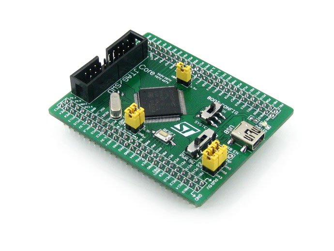
Core407V is a small STM32 development board that features an STM32F407VET6 device as the microcontroller, supports further expansion. It is ideal for starting application development with STM32F family.
As a minimal ready-to-run system, the Core407V integrates USB communication interface, JTAG/SWD programming/debugging interface, clock circuit, USB power management, boot mode selection, and so on.
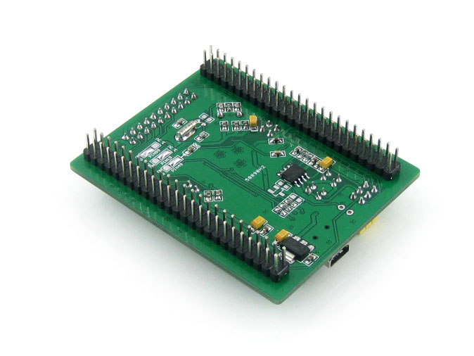
Furthermore, pin headers on the backside allow the Core407V to be plugged-in your application board and act as the MCU core circuit in your system. All the I/O ports are accessible on the pin headers, and the header pitch is designed as 2.54mm.
What's On Board
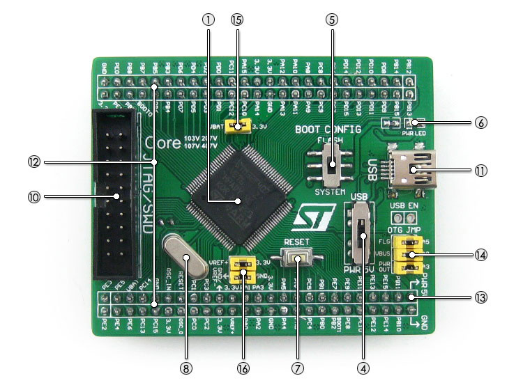
- STM32F407VET6:the high performance STM32 MCU which features:
- Core: Cortex-M4 32-bit RISC
- Feature: a full set of single-cycle DSP instructions
- Operating Frequency: 168MHz, 210 DMIPS/1.25 DMIPS/MHz
- Operating Voltage: 1.8V-3.6V
- Package: LQFP100
- Memories: 512kB Flash, 192+4kB SRAM
- MCU communication Interfaces:
- 3 x SPI, 3 x USART, 2 x UART, 2 x I2S, 3 x I2C
- 1 x FSMC, 1 x SDIO, 2 x CAN
- 1 x USB 2.0 high-speed/full-speed device/host/OTG controller with dedicated DMA, ULPI and on-chip full-speed PHY
- 1 x 10/100 Ethernet MAC
- 1 x 8 to 12-bit parallel camera interface
- AD & DA converters: 3 x AD (12-bit, 1μs, shares 24 channels); 2 x DA (12-bit)
- Debugging/Programming: supports JTAG/SWD (serial wire debug) interfaces, supports IAP
- AMS1117-3.3 (on bottom side): 3.3V voltage regulator
- MIC2075 (on bottom side): onboard USB power management device
- Power supply switch, powered from 5Vin or USB connection
- Boot mode switch, for configuring BOOT0 pin
- Power indicator
- Reset button
- 8M crystal oscillator
- 32.768K crystal (on bottom side), for internal RTC with calibration
- JTAG/SWD interface: for debugging/programming
- USB connector, used for establishing USB communication between PC and the STM32 development board
- IO expander (including VCC/GND), all the MCU pins are accessible on expansion connectors for further expansion
- 5Vin pinheader, 5V power supply is required when using USB HOST/OTG
- USB jumper
- short the jumper when using USB
- open the jumper to disconnect from I/O ports
- VBAT selection jumper
- short the jumper to use system power supply
- open the jumper to connect the VBAT to external power, such as battery
- VREF selection jumper
- short the jumper to connect VREF+/VREF- to VCC/GND
- open the jumper to connect VREF+/VREF- to other custom pin via jumper wire
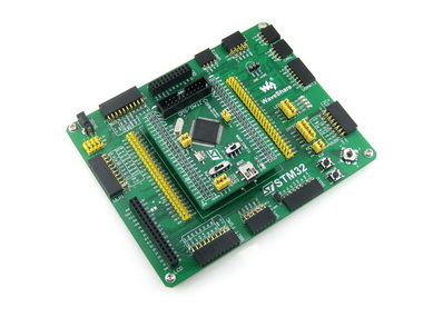
Photos
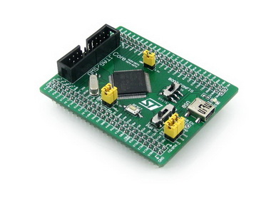


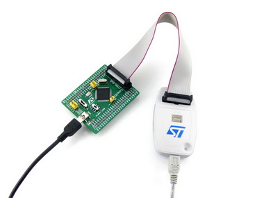
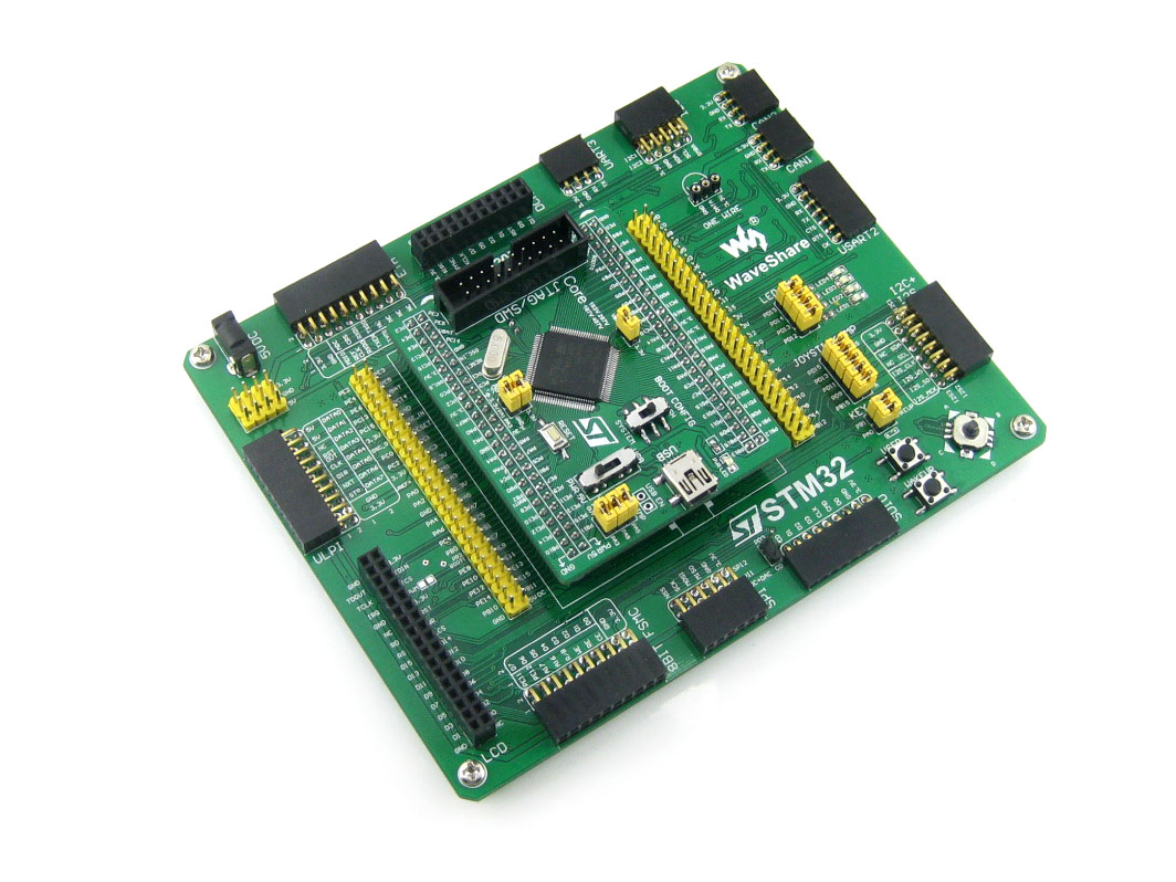
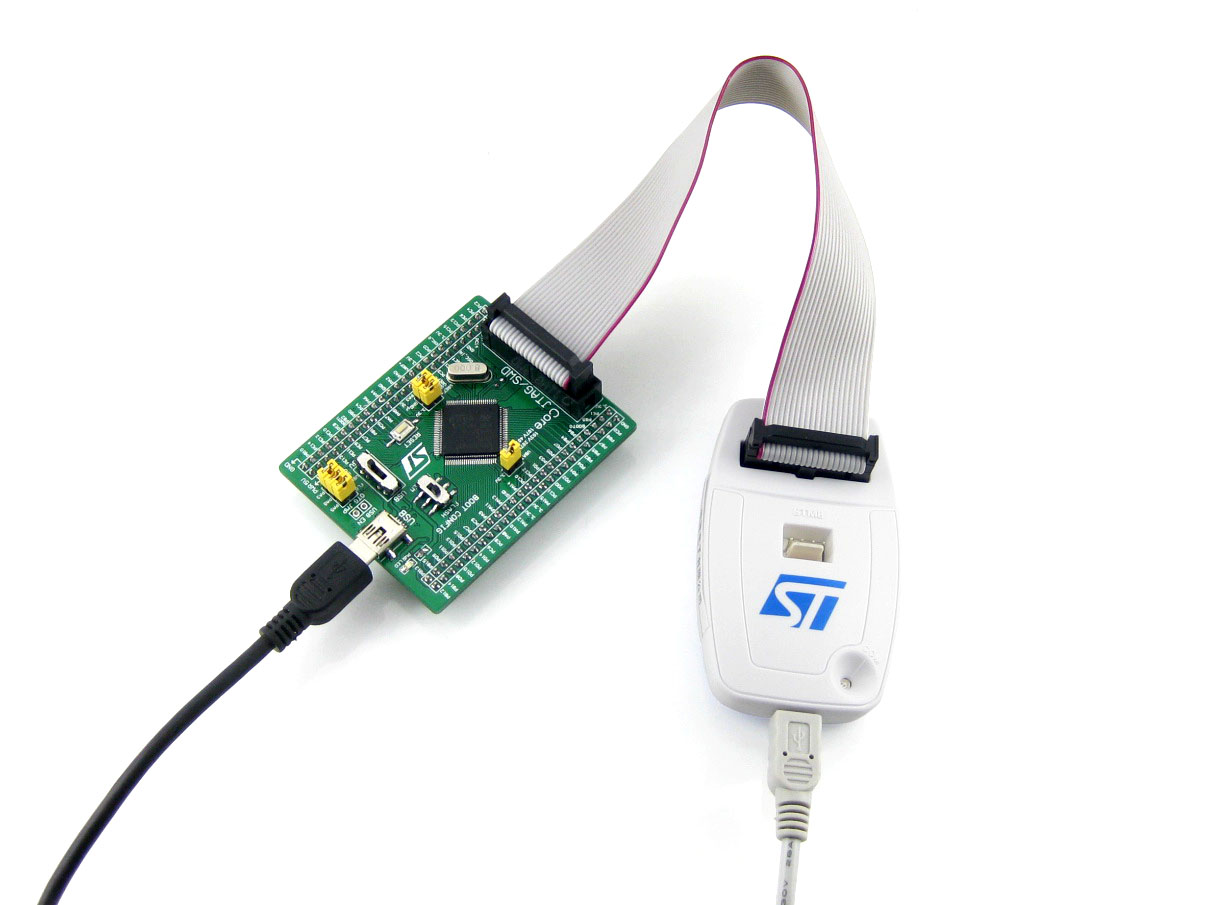
Note:
Core407V provides JTAG/SWD debugging interface, yet does NOT integrate any debugging function, a debugger is required.
Mother board and programmer/debugger in the photos are NOT included in the price.
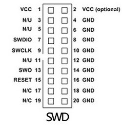
JTAG/SWD Interfaces
The figure 1, figure 2 shows the header pinout of JTAG, SWD interface respectively
Figure 1. JTAG Header Pinout
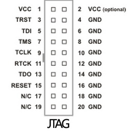
Figure 2. SWD Header Pinout
Development Resources
- Related software (KEIL etc.)
- Examples in C
- Schematic (PDF)
- Development documentations
Wiki: www.waveshare.com/wiki/Core407V
Dimensions
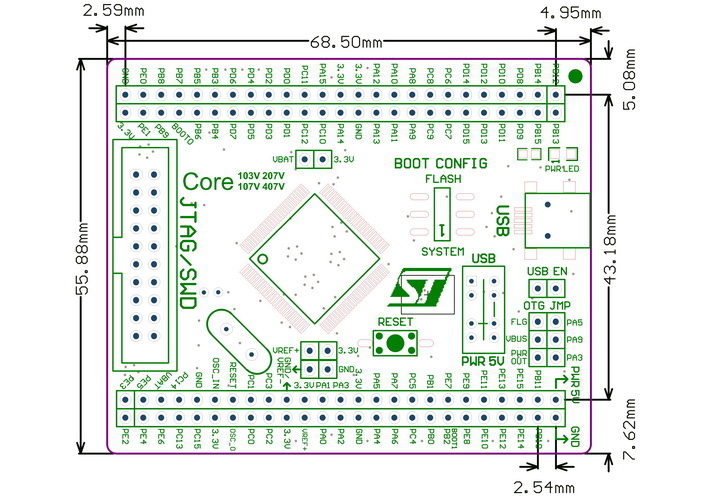
- STM32F407VET6:the high performance STM32 MCU which features:
- PACKAGE CONTENT
-
Weight: 0.104 kg
- Core407V development board x 1
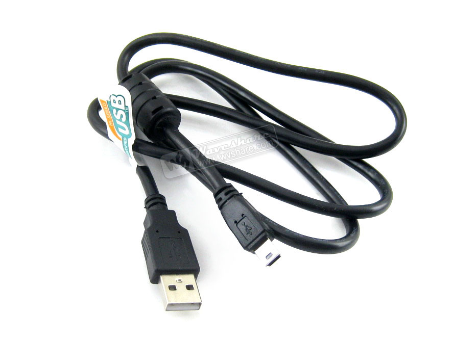
- USB type A to Mini-B cable x 1
- Software CD x 1
1

2

3


Điện tử ProE cung cấp linh kiện điện tử, thiết bị điện tử , linh kiện IoT chính hãng. ProE cung cấp dịch vụ đặt hàng linh kiện điện tử, thiết bị điện tử chính hãng theo yêu cầu cụ thể của khách hàng. Liên hệ : contact@proe.vn, SĐT: 0938946849
Website: www.proe.vn
Diễn đàn: https://www.facebook.com/groups/278263459284765/
Youtube Chanel: ProE Youtube
Facebook: ProE Facebook
Sản phẩm cùng loại
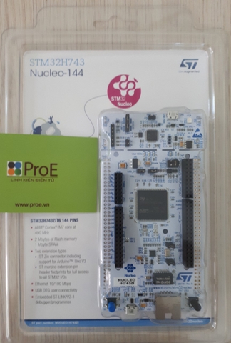
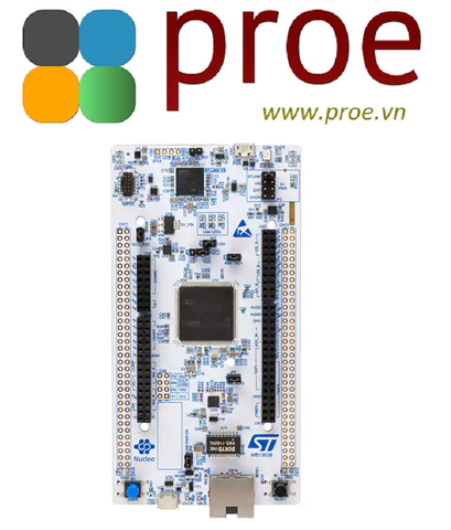
NUCLEO-H743ZI2
1.400.000₫
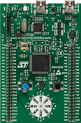
STM32F3 DISCOVERY
600.000₫
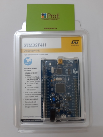
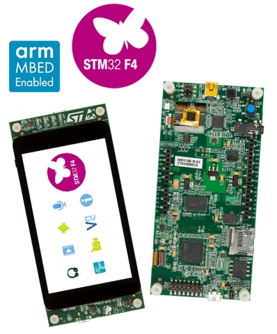
STM32F411 DISCOVERY
780.000₫

STM32F407G-DISC1
900.000₫
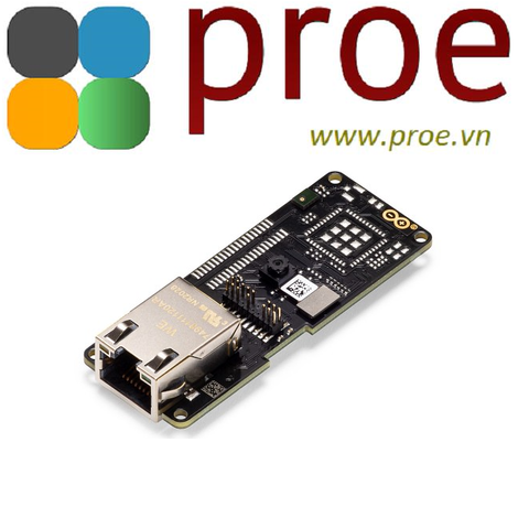
ASX00021 ARDUINO PORTENTA VISION SHIELD
1.950.000₫

NUCLEO-H723ZG
1.650.000₫
